Resets are one of the most critical signals in a design. ‘What is a reset?’ discusses all the basics about them. An issue with asynchronous reset was mentioned in this article, which is, de-assertion of asynchronous reset. If this de-assertion occurs close to an active clock edge, it violates the timing and causes metastability.
There are two phases of a reset:
Assertion:
- Activation of reset.
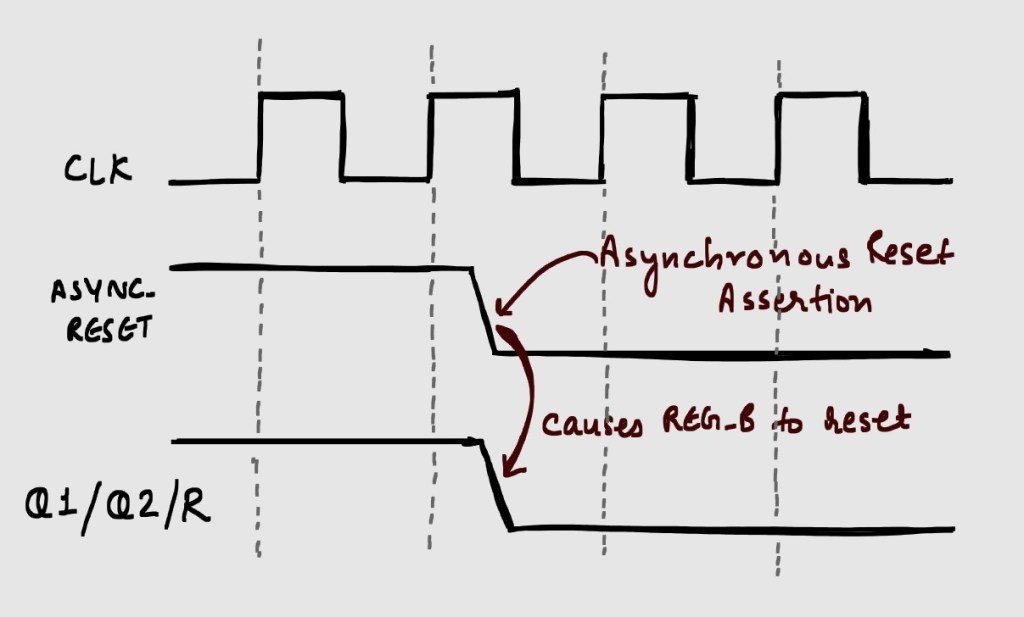
- This reset propagates to all the reset flops irrespective of the state of clock, and causes the design to be in reset state
- Asynchronous behavior works fine.
De-Assertion:
- Releasing the reset.
- System waits for the clock edge to detect the reset and the design goes out of reset state.
- Synchronous behavior of reset is the requirement.
A ‘Reset Synchronizer’ is a circuit used with asynchronous resets to achieve both the above requirements during assertion/de-assertion. The circuit consists of two flops with reset connected to the asynchronous reset, and D input of first flop is connected to VDD or ‘1’. The output of second flop acts as the new ‘Reset’ for the whole design, as shown in Figure 1.

The behavior of circuit in two phases is given below. We are assuming an active low reset with ‘0’ being the reset-active value, and ‘1’ being the reset-inactive value.
Assertion:
- Both flops are reset asynchronously (goes from ‘1’ to ‘0’)
- Node ‘R’ goes to reset state i.e. ‘0’ and resets the whole design
- Behaves like a normal asynchronous reset.
De-assertion:
- Asynchronous reset is de-asserted (goes from ‘0’ to ‘1’).
- On the first clock edge, VDD or ‘1’ value propagates through REG_A to Q1. The value at Q2 still remains ‘0’.
- On the second clock edge, VDD or ‘1’ propagates through REG_B to Q2.
- The value ‘1’ at second clock edge acts as the new ‘RESET’ for the whole design (behavior becomes synchronous).

The Verilog structure for this design in an ‘always’ block is given below:
always @ (posedge clk, negedge rst_n)
if(!rst_n) begin
Q1 <= 1’b0;
Q2 <= 1’b0;
end else begin
Q1 <= 1’b1;
Q2 <= Q1;
end
end
There are two terms w.r.t. timing for Reset signal:
Reset Recovery Time: This is the time between reset de-assertion and the time where active edge of clock goes high. (acts like a setup check)
Reset Removal Time: This is the time between active clock edge and reset de-assertion. (acts like a hold check)
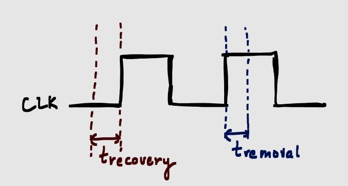
The reset de-assertion during these times is avoided to prevent metastability. Reset Synchronizer has 2 registers (like a normal data synchronizer), where first flip-flop synchronizes the reset signal and the second flip-flop removes any metastability that might have been caused.

Leave a reply to D O Cancel reply