When we talk about digital design, the language we use are HDLs (Hardware Description Language). Verilog is one such language which is used to create most of the designs. To get started with Verilog, lets study a simple 4 bit up-counter.
Function:
This counter is a 4 bit counter, i.e. it can count up to 2^4 (=16) values. In hexadecimal format, we can read these values as:
0,1,2,3,4,5,6,7,8,9,a,b,c,d,e,f
This is an up-counter i.e. it counts the values in an incremental manner.
Characteristics:
- Counter resets to the value ‘0’ when RESET is asserted i.e. RESET = 0. The counter starts again as soon as RESET becomes ‘1’.
- When counter exceeds the value ‘f’, it goes back to ‘0’ and starts counting again.
- The counter increments the value at the positive edge of the clock.
- The reset used here is an asynchronous reset. Read more about types of resets here.
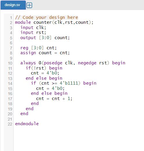
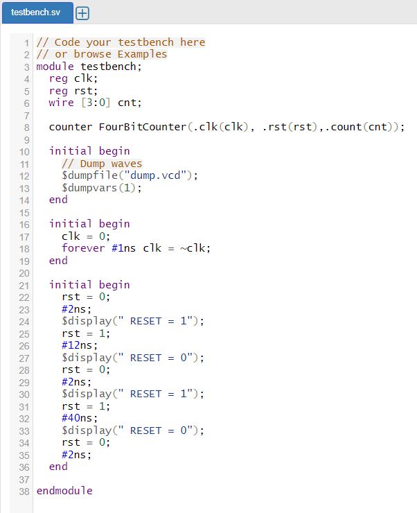
Code:
The code for the module ‘counter’ and its test bench is:
https://www.edaplayground.com/x/DS2x (Click on this link to run it and experiment on your own).
Waveforms:

- As RESET goes to ‘1’ at point ‘A’, the counter starts counting up.
- RESET goes to ‘0’ at point ‘B’, the counter resets to the value ‘0’.
- RESET goes to ‘1’ again at point ‘C’, and the counter starts counting up from the first positive clock edge after it.
- The counter keep counting until point ‘D’ when the counter value becomes ‘f’ (the highest possible value). The value automatically goes to ‘0’ again and counting continues.
- RESET goes to ‘0’ at point ‘E’ and counter resets to 0 again.
Find the code and waveform on :

Leave a comment