Boundary Scan Registers
Boundary scan testing consists of certain registers as mentioned in Boundary Scan-II. There are two kinds of registers:
Instruction registers: As the name implies, this register stores the instructions which can be decoded and executed as per requirements.
Data registers: Data registers are selected based on the decode instruction from the instruction register. There are three kinds of data registers which are:
- Bypass register: Bypassing all the testing structures, this register transfers data from TDI to TDO.
- Identity/IDCODE register: This register holds the identity code of the device. There is an instruction to read this code which will be discussed later along with other boundary scan instructions.
- Boundary Scan Register: This article will discuss Boundary Scan Register(BSR) in detail. BSR forms a chain along the ports of a design to allow testing.
A simplified representation of input and output BSR is given below.
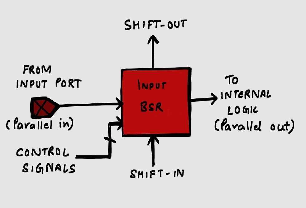
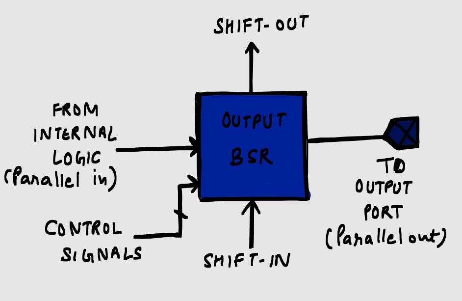
The control signals depicted in the figure are: Shift-DR, Capture-DR and Update-DR.
These control signals come from TAP FSM as discussed in Boundary Scan/JTAG-II. TAP FSM generates these control signals based on TMS and TCK inputs. Boundary scan register can be put on input/output or bidirectional ports (Bi-di ports have an input BSR, an output BSR and a control BSR). Lets discuss a typical output BSR, which is given in Figure 3.
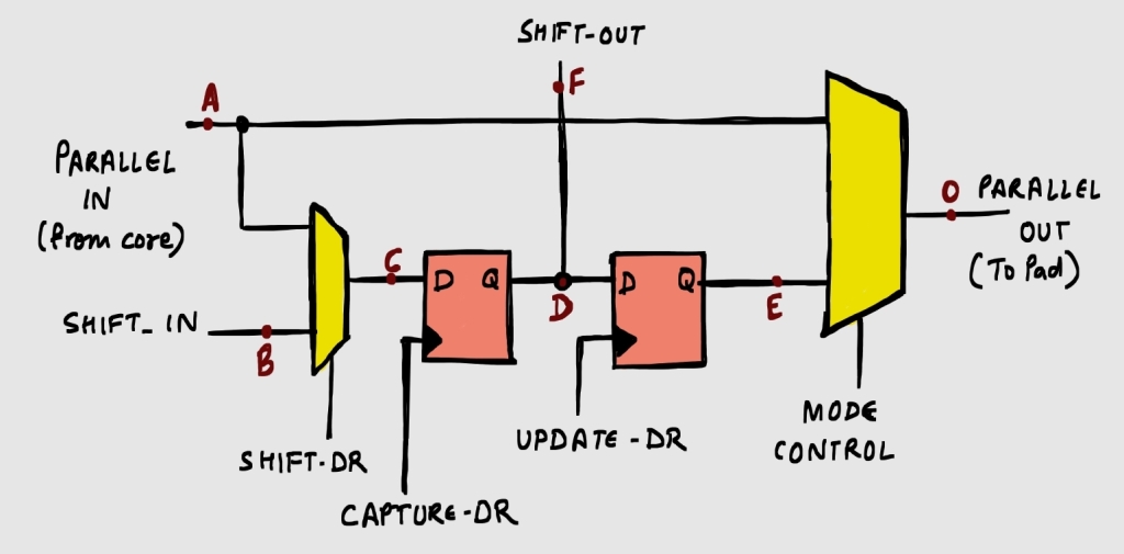
‘Mode_ctrl’ signal acts as select signal for the mux which selects between normal (functional) mode and test mode.
Normal mode
- Parallel data in -> Parallel data out
- (testing structure is not disturbed)
Test mode
- shift data in -> shift data out
- capture data (from internal logic)
- update data to output port
Test Mode Explained
Shift Operation:
Using Shift_DR control signal, either
- Test data from previous BSR is shifted in
- Observed data from internal logic is shifted in
It is generally used to shift known test data in instruction/data registers.
Capture operation:
Capture_DR can capture any data at ‘C’ brought in by shift operation.
Firstly, it is used to capture real data from internal logic (data at ‘A’ can be captured at ‘D’). This captured data can be shifted out via shift_out to be observed through TDO.
Secondly, this is also used to transfer data from shift_in to shift_out (‘B’ to ‘F’) to connect multiple BSRs in boundary scan chain, and read data from TDO.
Update operation:
Update_DR is used to update data at ‘D’ to ‘E’ and bring it to the output port ‘O’.
For input BSR, this is essentially used to transfer shift_in data (test data) to the internal logic.
For output BSR, this is essentially used to transfer real captured data (from internal logic) to the output port.
Additional Points
- Shift_DR acts as a MUX select signal while Capture_DR and Update_DR act as clock signals.
- Data can flow from shift_in to shift_out without disturbing data in hold section ‘E’ (which can be routed to output port through multiplexer).
The above mentioned modes (normal, shift, capture, update) are executed based on the instructions in the test. There are certain mandatory and optional instructions in boundary scan testing, which will be discussed in further articles. It will help you to understand the sequence of execution of shift/capture/update operation.

Leave a comment