Timing Paths
The basics of timing verification have been covered in the article ‘Timing verification – I‘. Please go through ‘setup and hold time‘ to refresh your concepts. This article will focus on the timing paths.
There are four kinds of timing paths that can be found in a design:
- Primary input to the data input of storage element (input to register)
- Output of storage element to data input of storage element (register to register)
- Output of a storage element to primary output (register to output)
- Primary input to primary output (Input to output)
Every path goes through a combinational logic.
- Tclock_delay: The delay in clock path due to skew or any buffer along clock path.
- Tcomb: Combinational path delay
- Tperiod: Clock period
- Tsetup: Setup time of capture flop
Register to Register
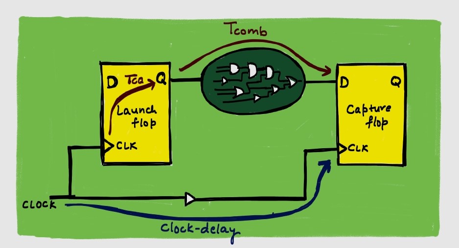
- Startpoint: CK pin of launch flop
- Endpoint: D pin of capture flop
- Arrival Time: Tcq + Tcomb
Setup Check:
- Required Time: Tperiod + Tclock-delay – Tsetup
- Arrival time < Required time
- Tcq + Tcomb < Tperiod + Tclock_delay – Tsetup
Hold Check:
- Required Time: Thold + Tclock_delay
- Arrival time > Required time
- Tcq + Tcomb > Thold + Tclock_delay
Input To Register
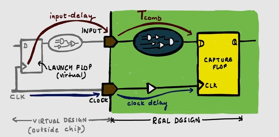
Input port receives data after ‘input delay’ as it is assumed to be launched from a flop outside the design (a virtual network).
- Startpoint: Input port
- Endpoint: D pin of capture flop
- Assumption: Launch flop is outside the real design (virtual design)
- Arrival time: Tinput_delay + Tcomb
Setup Check:
- Required time: Tperiod + Tclock_delay – Tsetup
- Arrival time < Required time
- Tinput_delay + Tcomb < Tperiod + Tclock_delay – Tsetup
Hold Check:
- Required Time: Thold + Tclock_delay
- Arrival time > Required time
- Tinput_delay + Tcomb > Thold + Tclock_delay
Register to Output
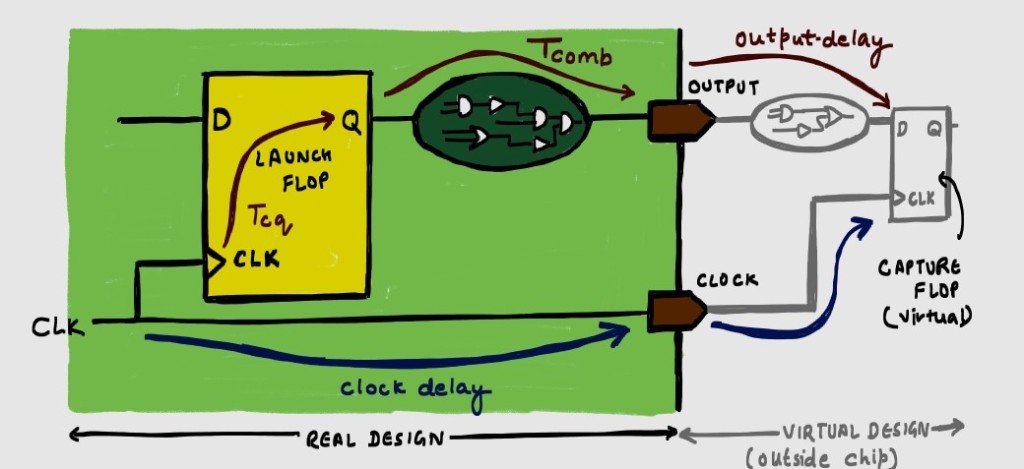
The register launches data to go to a capture flop, outside the real design through an ‘output port’. The time taken from output port to reach the virtual capture flop is Toutput_delay.
- Startpoint: CLK pin of launch flop
- Endpoint: Output port
- Assumption: Capture flop is outside the real design (virtual design)
- Arrival time: Tcq + Tcomb + Toutput_delay
Setup Check:
- Required time: Tperiod + Tclock_delay – Tsetup
- Arrival time < Required time
- Tcq + Tcomb + Toutput_delay < Tperiod + Tclock_delay – Tsetup
Hold Check:
- Required Time: Thold + Tclock_delay
- Arrival time > Required time
- Tcq + Tcomb + Toutput_delay > Thold + Tclock_delay
Input to Output

The analysis of Input to output can be done in the same way as register to register timing path, by assuming launch and capture flops outside real-design (virtual flops).
Additional Points:
Clock Uncertainty:
is subtracted from clock period, when calculating the slack for setup time.
Slack:
- Slack = Required time – Arrival time (for setup)
- Slack = Arrival time – Required time (for hold)
- Slack should always be positive. Negative slack indicates violation.
Choosing Combinational path:
While analyzing the combinational path for Tcomb, the tool chooses the longest path delay for max delay calculation (setup) and shortest path for min delay calculation (hold).
Choosing Max or Min delay values:
If the delays have minimum and maximum values, use them as follows:
For hold check:
- Data path : Minimum delay values
- Clock path: Maximum delay values
For setup check:
- Data path : Maximum delay values
- Clock path : Minimum delay values

Leave a comment